
- Joined
- Mar 1, 2004
- Posts
- 813
- Reaction score
- 1
CREDITS: Charles Allen (super-poser)
I had some problems with my Cruise Control(CC) which a few of you seem to have and found some good things on the internet. The only problem was, none of it worked in my case, every time I checked something turn, has access to some software that had the picture you see below and the troubleshooting guide that follows. Keep in mind, this requires a fair amount of electrical system familiarity and tools. For me, it rated fairly high on the DIY difficulty.
At any rate, you will want to check all vacuum possibilities before you continue with this guide. The vacuum from the pump under the jack at the front of the engine compartment on the driver's side, to the T junction just before the firewall, from the T junction to the actuator bulb, and from the T junction through the firewall to the
brake cut-off switch.
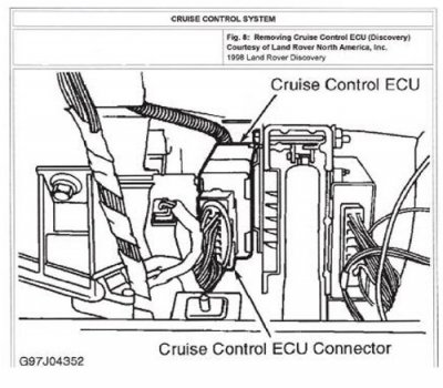
One other disclaimer here: My disco is a 98, I know for sure that the 96's are different, but am not sure when the change took place. Okay, you will need access to the Cruise Control ECU connector which is located
behind the glove box. Remove the glove box and you will see this (cruise pic):
Now, with a few tools for testing electrical circuits and some patience lets begin:
1. Turn ignition on. Turn CC system on. Put transfer case in HI range and gearshift in forward gear. (from this point forward I will say "in drive" to mean the previous sentence). Ensure clutch pedal is released. Disconnect cruise control ECU connector. Connect negative lead of voltmeter to CC ECU harness connector terminal no. 8 (black wire) and positive lead to terminal no. 10 (orange/white wire). If battery voltage exists, go to step 3. If battery voltage does not exist, go to next step.
2. Turn ignition off. Using ohmmeter, check resistance between ECU harness connector term. no. 8 (black wire) and ground. If resistance is less than one ohm, go to next step. if resistance is not less that one ohm, repair black wire between CC ECU and ground.
3. Ensure ignition and CC system are on. Disconnect CC ECU connector. Using voltmeter, check voltage between CC ECU harness connector term. no. 4 (red/yellow wire) and ground. With RESUME/DECEL switch pressed, battery voltage should exist. With RESUME/DECEL switch released, no voltage should exist. If voltage is as specified, go to next step. If voltage is not as specified check circuit from steering wheel switch to CC ECU.
4. Ensure ignition and CC system are on. Ensure CC ECU connector is disconnected. Using voltmeter, check voltage between CC ECU harness term. no. 3 (gray/yellow wire) and ground. With SET/ACCEL switch pressed, batter voltage should exist. With SET/ACCEL switch released, no voltage should exist. If voltage is as specified, go to next step. If voltage is not as specified, check circuit from steering wheel switch to
CC ECU.
5. Ensure ignition is on. Ensure CC ECU connector is disconnected. Using voltmeter, check voltage between CC ECU harness term no. 5 (green/purple wire) and ground. With brake pedal pressed, battery voltage should exist. With brake pedal released, no voltage should exist. If voltage is as specified, go to next step. If voltage is not as specified, check green/purple wire between CC ECU and stoplight switch. Check stoplight switch. Repair as necessary.
6. Turn ignition on. Reconnect CC ECU connector. Using voltmeter, back-probe between CC ECU harness term no. 11 (yellow wire) and ground. Spin a rear tire at about 3 MPH. Voltage should be about 2.5 volts, or vary between zero and 5 volts. If voltage is as specified, go to next step. If voltage is not as specified, check yellow
wire from CC ECU to the vehicle speed sensor. Check ECU. Repair as necessary.
7. Turn ignition on. Turn CC system on. Disconnect CC ECU harness connector. Connect a fused jumper wire between CC ECU harness term No. 1 (Orange/blue wire) and battery voltage. Connect another fused jumper wire between CC ECU harness term no. 7 (orange/red wire) and ground. If vacuum pump operates, go to
next step. If vacuum pump does not operate, check orange/blue and orange/red wires between CC ECU and vacuum pump. Check Vacuum pump. Repair as necessary.
8. Ensure ignition and CC system are on. Ensure CC ECU connector is disconnected. Connect a fuse jumper wire between CC ECU harness term. no. 1 (orange/blue wire) and battery voltage. Connect another fused jumper wire between CC ECU harness term. no. 7 (orange/red wire) and ground. Connect another fused jumper wire between CC ECU harness term. no. 6 (orange/pink wire) and ground. Vacuum pump should operate, valve should close and throttle should open wide. If system operates as specified, repair CC ECU. If system does not operate as specified, check orange/pink wire between CC ECU and vacuum pump. Check vacuum pump. Repair as necessary.
I hope this helps someone. It's a fairly easy way to diagnose any electrical or component problem with this cruise control system. Read: Do steps 7 and 8 to check your vacuum pump.
In my case the ECU was bad.
HTH, Good luck
Kit
P.S. This procedure is copyright 2001 MRIC and Snap-on Tools Company.
(I'd better give proper credit, right?)
I had some problems with my Cruise Control(CC) which a few of you seem to have and found some good things on the internet. The only problem was, none of it worked in my case, every time I checked something turn, has access to some software that had the picture you see below and the troubleshooting guide that follows. Keep in mind, this requires a fair amount of electrical system familiarity and tools. For me, it rated fairly high on the DIY difficulty.
At any rate, you will want to check all vacuum possibilities before you continue with this guide. The vacuum from the pump under the jack at the front of the engine compartment on the driver's side, to the T junction just before the firewall, from the T junction to the actuator bulb, and from the T junction through the firewall to the
brake cut-off switch.
One other disclaimer here: My disco is a 98, I know for sure that the 96's are different, but am not sure when the change took place. Okay, you will need access to the Cruise Control ECU connector which is located
behind the glove box. Remove the glove box and you will see this (cruise pic):
Now, with a few tools for testing electrical circuits and some patience lets begin:
1. Turn ignition on. Turn CC system on. Put transfer case in HI range and gearshift in forward gear. (from this point forward I will say "in drive" to mean the previous sentence). Ensure clutch pedal is released. Disconnect cruise control ECU connector. Connect negative lead of voltmeter to CC ECU harness connector terminal no. 8 (black wire) and positive lead to terminal no. 10 (orange/white wire). If battery voltage exists, go to step 3. If battery voltage does not exist, go to next step.
2. Turn ignition off. Using ohmmeter, check resistance between ECU harness connector term. no. 8 (black wire) and ground. If resistance is less than one ohm, go to next step. if resistance is not less that one ohm, repair black wire between CC ECU and ground.
3. Ensure ignition and CC system are on. Disconnect CC ECU connector. Using voltmeter, check voltage between CC ECU harness connector term. no. 4 (red/yellow wire) and ground. With RESUME/DECEL switch pressed, battery voltage should exist. With RESUME/DECEL switch released, no voltage should exist. If voltage is as specified, go to next step. If voltage is not as specified check circuit from steering wheel switch to CC ECU.
4. Ensure ignition and CC system are on. Ensure CC ECU connector is disconnected. Using voltmeter, check voltage between CC ECU harness term. no. 3 (gray/yellow wire) and ground. With SET/ACCEL switch pressed, batter voltage should exist. With SET/ACCEL switch released, no voltage should exist. If voltage is as specified, go to next step. If voltage is not as specified, check circuit from steering wheel switch to
CC ECU.
5. Ensure ignition is on. Ensure CC ECU connector is disconnected. Using voltmeter, check voltage between CC ECU harness term no. 5 (green/purple wire) and ground. With brake pedal pressed, battery voltage should exist. With brake pedal released, no voltage should exist. If voltage is as specified, go to next step. If voltage is not as specified, check green/purple wire between CC ECU and stoplight switch. Check stoplight switch. Repair as necessary.
6. Turn ignition on. Reconnect CC ECU connector. Using voltmeter, back-probe between CC ECU harness term no. 11 (yellow wire) and ground. Spin a rear tire at about 3 MPH. Voltage should be about 2.5 volts, or vary between zero and 5 volts. If voltage is as specified, go to next step. If voltage is not as specified, check yellow
wire from CC ECU to the vehicle speed sensor. Check ECU. Repair as necessary.
7. Turn ignition on. Turn CC system on. Disconnect CC ECU harness connector. Connect a fused jumper wire between CC ECU harness term No. 1 (Orange/blue wire) and battery voltage. Connect another fused jumper wire between CC ECU harness term no. 7 (orange/red wire) and ground. If vacuum pump operates, go to
next step. If vacuum pump does not operate, check orange/blue and orange/red wires between CC ECU and vacuum pump. Check Vacuum pump. Repair as necessary.
8. Ensure ignition and CC system are on. Ensure CC ECU connector is disconnected. Connect a fuse jumper wire between CC ECU harness term. no. 1 (orange/blue wire) and battery voltage. Connect another fused jumper wire between CC ECU harness term. no. 7 (orange/red wire) and ground. Connect another fused jumper wire between CC ECU harness term. no. 6 (orange/pink wire) and ground. Vacuum pump should operate, valve should close and throttle should open wide. If system operates as specified, repair CC ECU. If system does not operate as specified, check orange/pink wire between CC ECU and vacuum pump. Check vacuum pump. Repair as necessary.
I hope this helps someone. It's a fairly easy way to diagnose any electrical or component problem with this cruise control system. Read: Do steps 7 and 8 to check your vacuum pump.
In my case the ECU was bad.
HTH, Good luck
Kit
P.S. This procedure is copyright 2001 MRIC and Snap-on Tools Company.
(I'd better give proper credit, right?)