

- Joined
- Jun 28, 2004
- Posts
- 10,519
- Reaction score
- 199
Fixing non functional rear windows
by Don Herrero
(This was done on a 96 SE-7)
Tools required:
7mm socket w/ 2" extension
Small standard screwdriver
Soldering Iron
Solder
Time: 15 minutes
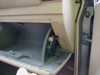
Remove the glove box. There are four 7mm screws that are at the hinge.
You then have to remove move the 2 spring latches on the sides to completely remove the box. (See fig.1)
Fig 1
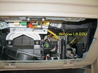
Locate the Window lift ECU (fig. 2) and remove the 2 wiring harnesses.
Also remove the two 7mm nuts holding the front of the ECU located at the top and bottom. (This will help in the removal of the circuit board)
The enclosure will not come out due to a fastener near the firewall.
Fig. 2
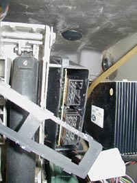
Pry off the plastic plate holding the board in the enclosure. (Fig. 3)
Fig. 3
Carefully slide the circuit board out. You will have to do some careful positioning of the enclosure to get the board out.
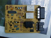
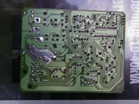
Fig. 4 & 5 show the board removed.
Fig. 4
Fig. 5
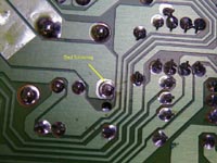
Here is where my board failed due to bad soldering (Fig. 6)
Fig. 6
Check all suspect solder connections and re-solder.
Installation is the reverse of removal.
by Don Herrero
(This was done on a 96 SE-7)
Tools required:
7mm socket w/ 2" extension
Small standard screwdriver
Soldering Iron
Solder
Time: 15 minutes
Remove the glove box. There are four 7mm screws that are at the hinge.
You then have to remove move the 2 spring latches on the sides to completely remove the box. (See fig.1)
Fig 1
Locate the Window lift ECU (fig. 2) and remove the 2 wiring harnesses.
Also remove the two 7mm nuts holding the front of the ECU located at the top and bottom. (This will help in the removal of the circuit board)
The enclosure will not come out due to a fastener near the firewall.
Fig. 2
Pry off the plastic plate holding the board in the enclosure. (Fig. 3)
Fig. 3
Carefully slide the circuit board out. You will have to do some careful positioning of the enclosure to get the board out.
Fig. 4 & 5 show the board removed.
Fig. 4
Fig. 5
Here is where my board failed due to bad soldering (Fig. 6)
Fig. 6
Check all suspect solder connections and re-solder.
Installation is the reverse of removal.
 ) of Automotive Goop (I think an epoxy would work as well) next to each relay and also joining each relay to the others which ties these relays to the board and takes the load off the solder joint. Just my working hypothesis right now - time will tell - but something to think about. Russ