
Second Battery--
Sears Platinum Group 34 Sears Item# 02850034000 | Model# P-1
A dual post Marine Version is also available for the same price. $219.
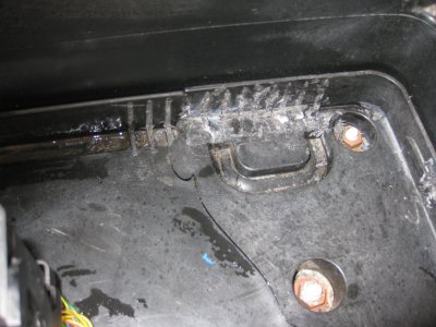
I had to cut the plastic ribs in front of the battery box and notch the inside rib to clear the Sears Group 34 battery.
The metal LR hold down supplied by Traxide is for the Land rover style battery, which also works with the Optima. The raised portion does nothing and the width is too small for the Sears/Odyssey.
A new clamp needed to be made. I used a plastic scrap channel.
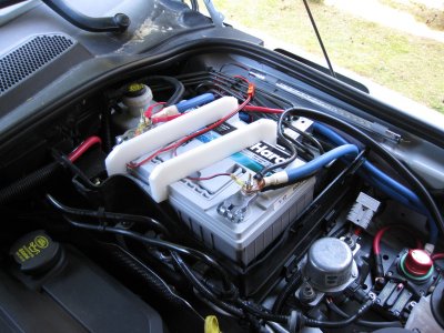
I added a 4 Ga. utility pigtail with a 50 amp Anderson connector directly to the battery.
I added a 30 amp Anderson connector directly to the battery and attached a LED light strip to the fender well.
I added a CTEK battery charger socket to both batteries for easy attachment of my CTEK battery charger.
Traxide 160 Mounting--
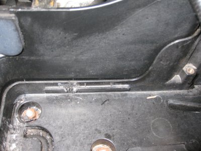
The Traxide mounts inside the (RtHD) battery box.
The supplied positive cable comes across from the starting battery and enters the new battery box in a slot near the firewall. The supplied short positive cable drops from the positive terminal of the Aux battery to the Traxide module. The aux battery ground goes to the stock ground post near the firewall. Mount the display box on the dash, hook up the 4 wires and read the LED decoding flashes.
Cabling the power to the rear area--
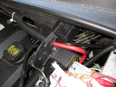
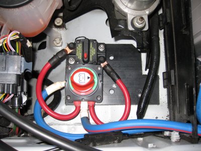
I wanted to be able to disconnect the rear power service near the source battery. I used a small marine switch (240 amp) made for two batteries. All of the wires are positive so the proximity is not an issue. The switch is mounted on a 3/8” plastic plate screwed to the area in front of the battery box. I wanted to be able to send high current to the rear if I ever use a winch and also be able to have a fused mode for normal use. I added a 100 amp resettable marine breaker (Buss) by putting the breaker across the two output posts on the switch. The breaker is bolted next to the switch. Think of this as constructive misuse of a component. The removable side covers on the switch allows access to the ¼” output posts. The 2 Ga. positive wire run to the rear, goes here. The positive wire from the Aux. battery goes to the switch input. The 2 ga. Ground wire goes to the stock ground post. I now have the choices of OFF, position 1 for unfused power to the rear and position 2 for fused power to the rear.
Cheer, Roy
Sears Platinum Group 34 Sears Item# 02850034000 | Model# P-1
A dual post Marine Version is also available for the same price. $219.
I had to cut the plastic ribs in front of the battery box and notch the inside rib to clear the Sears Group 34 battery.
The metal LR hold down supplied by Traxide is for the Land rover style battery, which also works with the Optima. The raised portion does nothing and the width is too small for the Sears/Odyssey.
A new clamp needed to be made. I used a plastic scrap channel.
I added a 4 Ga. utility pigtail with a 50 amp Anderson connector directly to the battery.
I added a 30 amp Anderson connector directly to the battery and attached a LED light strip to the fender well.
I added a CTEK battery charger socket to both batteries for easy attachment of my CTEK battery charger.
Traxide 160 Mounting--
The Traxide mounts inside the (RtHD) battery box.
The supplied positive cable comes across from the starting battery and enters the new battery box in a slot near the firewall. The supplied short positive cable drops from the positive terminal of the Aux battery to the Traxide module. The aux battery ground goes to the stock ground post near the firewall. Mount the display box on the dash, hook up the 4 wires and read the LED decoding flashes.
Cabling the power to the rear area--
I wanted to be able to disconnect the rear power service near the source battery. I used a small marine switch (240 amp) made for two batteries. All of the wires are positive so the proximity is not an issue. The switch is mounted on a 3/8” plastic plate screwed to the area in front of the battery box. I wanted to be able to send high current to the rear if I ever use a winch and also be able to have a fused mode for normal use. I added a 100 amp resettable marine breaker (Buss) by putting the breaker across the two output posts on the switch. The breaker is bolted next to the switch. Think of this as constructive misuse of a component. The removable side covers on the switch allows access to the ¼” output posts. The 2 Ga. positive wire run to the rear, goes here. The positive wire from the Aux. battery goes to the switch input. The 2 ga. Ground wire goes to the stock ground post. I now have the choices of OFF, position 1 for unfused power to the rear and position 2 for fused power to the rear.
Cheer, Roy